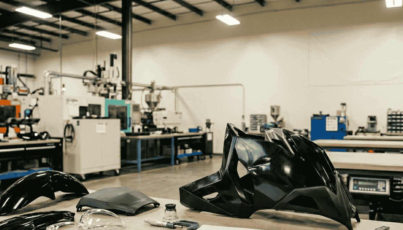
Plastic components play a critical role in modern motorcycle design, from aerodynamic fairings and side covers to functional housings and protective elements.
These parts are not only required to meet structural and thermal performance criteria but also maintain high cosmetic standards, especially for exposed surfaces.
However, in high-volume manufacturing, injection molding defects remain one of the most common challenges affecting product quality, production efficiency, and overall cost.
Defects can lead to increased scrap rates, rework, and assembly issues, ultimately impacting delivery timelines and supplier reliability.
From an engineering standpoint, injection molding defects are rarely caused by a single issue. Instead, they result from complex interactions between material properties, mold design, and process parameters.
Understanding these relationships is essential for preventing defects rather than reacting to them during production.
Overview of Injection Molding Defects
Injection molding defects are defined as deviations from the intended part geometry, dimensional accuracy, surface finish, or internal structural integrity, typically resulting from imbalances in material behavior, mold design, or process parameters during molding.
In motorcycle applications, defect control becomes significantly more critical due to the dual requirement of mechanical performance and Class-A surface appearance.
From a manufacturing perspective, defects can be broadly classified into:
1. Visual defects: such as sink marks and flow lines, typically associated with non-uniform cooling, inconsistent flow front behavior, or inadequate packing pressure.
2. Structural defects: including warpage and internal voids, often driven by residual stress, differential shrinkage, or poor gate and cooling design.
3. Surface defects: such as burn marks and weld lines, usually linked to air entrapment, improper venting, or suboptimal flow convergence.
For externally exposed motorcycle components, such as fairings, covers, and trim parts, even minor visual imperfections can lead to part rejection, not only from a quality standpoint but also from brand perception and customer acceptance.
As a result, defect prevention must be addressed early at the design and tooling stage, rather than relying solely on process adjustments during production.
Common Injection Molding Defects in Motorcycle Components
Sink Marks
Sink marks are localized surface depressions that typically occur in areas with non-uniform wall thickness, particularly around ribs, bosses, or reinforced features. These defects are primarily driven by differential cooling and insufficient packing compensation during the material solidification phase.
From a design-for-manufacturability (DFM) standpoint, the root cause is often excessive thickness at structural features relative to the nominal wall. When the core region cools slower than the surface, volumetric shrinkage is not fully compensated, resulting in visible surface collapse.
In motorcycle components especially exterior parts such as fairings, sink marks are unacceptable due to their direct impact on perceived surface quality.
Controlling rib-to-wall thickness ratio (typically 50–60% of nominal wall) and optimizing packing pressure profile are critical to mitigate this issue without introducing additional cycle time or internal stress
Warpage
Warpage refers to the distortion of a molded part due to non-uniform shrinkage and residual stress distribution. This defect is particularly critical in large, thin-walled motorcycle components where dimensional stability directly affects downstream assembly.
The primary drivers include uneven cooling rates across the mold, suboptimal cooling channel layout, and material-related anisotropy, especially in fiber-filled polymers where shrinkage varies by orientation. Gate location and flow path also play a significant role in defining stress distribution during solidification.
From a functional perspective, warpage can lead to misalignment during assembly, increased fastening stress, and inconsistent gap appearance between mating parts.
For OEM-level applications, this directly translates into rejection risk and additional rework. Early-stage mold flow simulation and balanced cooling design are essential to control warpage at scale.
Weld Lines (Knit Lines)
Weld lines are formed when two or more (melt fronts) converge but fail to achieve full molecular entanglement. This typically occurs in areas where flow is interrupted by holes, inserts, or complex geometries.
Beyond being a visual defect, weld lines represent localized due to incomplete bonding at the interface. The severity depends on melt temperature, injection speed, and pressure at the point of convergence.
In motorcycle applications, weld lines must be carefully evaluated in load-bearing or vibration-sensitive regions. Poorly positioned weld lines can become initiation points for cracking under cyclic loading. Strategic gate placement, higher melt temperature, and proper venting are commonly used to improve weld line strength.
Flow Lines
Flow lines appear as visible streaks or wave-like patterns on the part surface, resulting from variations in melt flow velocity and cooling rate during cavity filling.
They are commonly associated with suboptimal processing conditions such as low melt temperature, inconsistent injection speed, or abrupt transitions in wall thickness that disrupt flow front stability. These variations create differences in surface gloss and texture, making them highly visible on aesthetic components.
While often categorized as cosmetic defects, flow lines can also indicate poor flow consistency, which may affect material packing and dimensional accuracy. Maintaining a stable flow front through optimized injection profile and uniform wall design is key to preventing this issue.
Burn Marks
Burn marks are localized discolorations, typically dark brown or black, caused by trapped air that undergoes compression and overheating during the filling phase.
These defects usually occur at end-of-fill regions or in areas with inadequate venting. In addition to aesthetic degradation, burn marks indicate excessive localized temperature, which can lead to material degradation and reduced mechanical properties.
From a tooling perspective, insufficient vent depth or poor vent placement is a common root cause. Proper venting design, combined with controlled injection speed to avoid air entrapment, is essential for stable and repeatable production.
Short Shots
Short shots occur when the molten material fails to completely fill the mold cavity, resulting in incomplete or partially formed parts. This defect is typically caused by insufficient injection pressure, premature solidification, or flow restriction within the mold.
In motorcycle components with thin sections or complex geometries, the risk of short shots increases significantly due to higher flow resistance and faster cooling rates. Gate size, runner design, and material flow length-to-thickness ratio become critical design parameters.
From a production standpoint, short shots are high-risk defects as they directly impact functionality and cannot be reworked. Ensuring adequate flowability through proper material selection, optimized gate design, and sufficient injection pressure is essential for maintaining production reliability.
Root Causes: Engineering Perspective
To effectively control and prevent injection molding defects, root cause analysis must be approached holistically across three interdependent domains: material selection, mold design, and process parameters.
In practice, defects rarely originate from a single factor; instead, they result from the interaction between these variables under real production conditions.
1. Material Selection
Thermoplastic materials exhibit distinct rheological behavior, shrinkage characteristics, and thermal properties, all of which directly influence flow behavior and dimensional stability during molding.
For example, amorphous materials such as ABS and PC generally provide better dimensional stability with lower and more uniform shrinkage, while semi-crystalline materials like PP exhibit higher shrinkage variability and are more sensitive to cooling conditions.
These differences become more pronounced in complex geometries or thin-wall applications where flow length and cooling rate are critical.
Improper material selection, particularly without considering flowability, shrinkage rate, and application-specific mechanical requirements can significantly increase susceptibility to defects such as warpage, sink marks, and flow instability.
From an engineering standpoint, material selection must be aligned not only with functional requirements but also with manufacturability constraints.
2. Mold Design
Mold design defines the physical boundary conditions of the injection molding process and is often the most decisive factor in defect prevention. Even with optimal material and machine settings, a suboptimal mold design will systematically introduce variability and defects.
Key design parameters include:
1. Gate location and type: Determines flow pattern, pressure distribution, and weld line positioning
2. Runner system balance: Ensures uniform filling across cavities, particularly in multi-cavity molds
3. Cooling channel design: Directly impacts heat dissipation rate, cycle time, and shrinkage uniformity
4. Venting efficiency: Critical for preventing air entrapment, burn marks, and incomplete filling
From a DFM perspective, early-stage validation using mold flow simulation is essential to predict potential defect zones and optimize tooling design before fabrication. This is particularly important for motorcycle components with complex surfaces and aesthetic requirements.
3. Process Parameters
Process parameters govern how material behaves within the constraints defined by the mold.
Key variables such as injection pressure, melt temperature, injection speed, packing pressure, and cooling time must be precisely controlled and matched to both material properties and part geometry.
For example, insufficient packing pressure can lead to sink marks and internal voids, while excessive injection speed may cause air entrapment or burn marks. Similarly, inadequate cooling time can result in warpage due to incomplete solidification and residual stress release after ejection.
In a production environment, process inconsistency, whether due to machine variation, environmental conditions, or lack of process window control often becomes the dominant source of recurring defects.
Establishing a robust processing window and maintaining parameter stability are therefore critical for achieving repeatable part quality at scale.
Prevention Strategies for Injection Molding Defects
Effective defect prevention in injection molding requires a proactive engineering approach that integrates part design, tooling strategy, material behavior, and process control.
Rather than relying on corrective actions during production, leading manufacturers prioritize early-stage decisions that minimize variability and ensure repeatable quality across production volumes.
Design for Manufacturability (DFM)
Implementing DFM principles at the product design stage is the most cost-effective method to eliminate potential defects before tooling investment is made. Poor geometric design will inherently introduce process instability, regardless of downstream optimization.
Key DFM considerations include:
1. Uniform wall thickness to ensure consistent cooling rates and minimize differential shrinkage
2. Optimized rib-to-wall thickness ratio (typically 50–60%) to provide structural support without inducing sink marks
3. Smooth geometric transitions (fillets over sharp corners) to maintain stable flow behavior and reduce stress concentration
From an engineering standpoint, DFM is not only about defect prevention but also about reducing cycle time, improving moldability, and ensuring long-term dimensional stability.
Optimized Mold Design
A well-engineered mold acts as the foundation for process stability and repeatability. Tooling decisions directly influence how material flows, cools, and solidifies, making mold design a critical control point for defect prevention.
Key considerations include:
1. Strategic gate positioning to control flow direction, minimize weld lines in critical areas, and ensure uniform pressure distribution
2. Adequate venting design to prevent air entrapment, which can lead to burn marks and short shots
3. Balanced cooling system layout to achieve uniform heat dissipation, reducing the risk of warpage and residual stress
In high-precision motorcycle components, even minor inconsistencies in mold design can result in cumulative quality issues across production batches. Therefore, tooling validation, often supported by simulation is essential prior to mass production.
Process Optimization
Process parameters must be developed and controlled using a structured, data-driven approach, commonly referred to as scientific molding. This ensures that the process operates within a defined and repeatable window rather than relying on trial-and-error adjustments.
Key practices include:
1. Material-specific parameter optimization, including melt temperature, injection speed, and packing profile based on rheological behavior
2. Cycle consistency monitoring, ensuring stable filling, packing, and cooling phases across each shot
3. Variation reduction across batches, through controlled machine settings, environmental stability, and standardized operating procedures
A robust process window not only reduces defect occurrence but also improves production efficiency and predictability key concerns for both manufacturing engineers and procurement teams.
Material Selection Strategy
selection must be approached as a combined engineering and manufacturing decision, rather than purely based on mechanical properties. Each material introduces specific processing characteristics that influence defect risk.
Key selection criteria include:
1. Thermal properties (e.g., heat resistance, glass transition temperature) affecting processing window and part performance
2. Mechanical performance (impact strength, stiffness) aligned with functional requirements
3. Shrinkage behavior and dimensional stability, particularly important for tight-tolerance or large surface components
For motorcycle applications, selecting the appropriate engineering plastic requires balancing performance requirements with flowability, moldability, and long-term production stability.
Incorrect material choices often lead to recurring defects that cannot be fully resolved through tooling or process adjustments alone.
Application in Motorcycle Industry
In motorcycle manufacturing, tolerance for injection molding defects is significantly lower compared to general consumer products due to the combination of structural performance requirements, tight assembly tolerances, and high visual exposure of components.
Unlike non-visible industrial parts, many motorcycle components must simultaneously meet mechanical durability standards and Class-A surface finish expectations.
From an engineering and production standpoint, defect sensitivity is closely tied to the function and positioning of each component within the vehicle system:
1. Fairings and large exterior panels
These components require strict control of warpage to maintain dimensional accuracy and consistent gap alignment during assembly.
Even minor deformation can lead to misfit issues, increased assembly stress, and visible inconsistencies between adjoining parts. This makes cooling uniformity, material shrinkage control, and gate strategy critical during both design and tooling stages.
2. Structural housings and functional components
Parts such as brackets, enclosures, and load-bearing housings must avoid weld lines in mechanically critical regions. Since weld lines represent potential (weak points) in the material structure, improper placement can reduce fatigue resistance and increase the risk of failure under vibration or cyclic loading conditions commonly experienced in motorcycle operation.
3. Covers, trims, and aesthetic panels
These components demand high surface quality, where defects such as flow lines, sink marks, or burn marks are immediately visible and unacceptable from a product quality perspective.
Achieving consistent surface finish requires not only optimized processing conditions but also well-controlled material flow behavior and mold surface quality.
This combination of aesthetic expectations and functional performance requirements elevates defect prevention from a quality control task to a core engineering responsibility.
As a result, early integration between product design, material selection, and tooling strategy is essential to ensure that components meet both performance and visual standards in mass production environments.
Common Mistakes in Production
In many injection molding operations, recurring defects are not caused by isolated issues but by systemic gaps in engineering integration and decision-making. A number of common mistakes often lead to persistent quality problems and unstable production performance:
1. Over-reliance on machine parameter adjustments
Attempting to resolve defects solely by modifying injection pressure, temperature, or cycle time often results in temporary improvements without addressing the underlying root cause. While process tuning is important, it cannot compensate for fundamental issues in part design or tooling.
2. Neglecting mold design optimization
Mold-related factors such as improper gate location, insufficient venting, or unbalanced cooling systems are frequently overlooked once tooling is completed. In practice, these limitations constrain the entire process window and make consistent defect control difficult to achieve.
3. Skipping DFM evaluation during early design stages
Bypassing DFM analysis during product development often leads to geometries that are inherently difficult to mold. This includes excessive wall thickness variation, poor rib design, or complex flow paths that increase the likelihood of defects such as sink marks, warpage, and short shots.
4. Using unsuitable materials for the application
Selecting materials based solely on mechanical specifications without considering processing behavior, such as flowability, shrinkage characteristics, and thermal stability can introduce persistent molding challenges that are difficult to resolve during production.
These approaches typically result in reactive, short-term fixes rather than establishing a stable and repeatable manufacturing process. Over time, this leads to increased rejection rates, inconsistent quality, and higher overall production costs.
Technical Consultation & RFQ Support for Motorcycle Plastic Parts
For OEMs and component suppliers developing motorcycle plastic components, early collaboration with an experienced manufacturing partner plays a critical role in ensuring design feasibility and production efficiency.
By engaging in technical discussions during the early development stage, key factors such as wall thickness distribution, structural reinforcement, material performance, and moldability can be properly evaluated before tooling investment is made.
Banshu Plastic Indonesia supports motorcycle injection molding projects through a structured engineering approach, including Design for Manufacturability (DFM) analysis, material selection guidance, and optimized mold design.
This ensures that components such as fairings, housings, and covers can achieve consistent dimensional accuracy, reliable performance, and stable mass production output.
Engineering teams and procurement professionals can submit 3D part drawings for a technical feasibility review or request RFQ support to assess suitable material options, tooling strategies, and production scalability.
For technical consultation or to discuss your project requirements, contact our engineering team to initiate a DFM evaluation and explore manufacturing solutions aligned with your product specifications and production targets.