
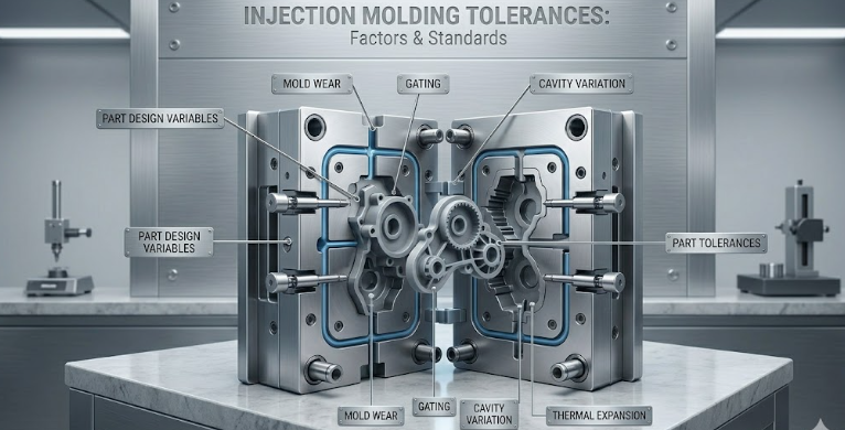
Dimensional tolerance is one of the most critical aspects of injection molding, particularly for products that depend on assembly precision, sealing performance, structural alignment, or repeatable mechanical movement.
In industrial production, a molded plastic part is rarely evaluated only by its visual appearance.
More often, the real challenge lies in whether the component can maintain dimensional consistency across long production runs while still meeting functional requirements.
Many engineers entering plastic product development from machining or metal fabrication backgrounds initially assume that tolerances in injection molding behave similarly to CNC-machined parts.
In reality, thermoplastics behave very differently from metals during manufacturing. Injection molding is a thermal process involving molten polymer flow, pressure packing, cooling, crystallization, and post-molding dimensional stabilization.
Because of this, dimensional variation is an inherent characteristic of molded plastic components.
This is why injection molding tolerances are influenced by much more than cavity machining precision alone. Material shrinkage, wall thickness distribution, gate location, cooling balance, molecular orientation, and process stability all contribute to the final dimensional result.
Understanding what is realistically achievable in production is essential not only for product designers, but also for tooling engineers, sourcing teams, and manufacturing engineers responsible for long-term process stability.
Understanding Tolerance in Injection Molding
In manufacturing terminology, tolerance refers to the allowable dimensional variation from a nominal specification. A feature dimensioned at 50.00 mm, for example, may permit a limited dimensional range depending on product functionality and assembly requirements.
In injection molding, however, the nominal CAD dimension does not directly represent the final molded dimension.
Thermoplastics shrink as they cool from melt temperature to ambient temperature, and the amount of shrinkage varies depending on material type, geometry, pressure distribution, and cooling behavior.
This means injection molding is fundamentally a shrinkage-controlled manufacturing process.
Unlike machining processes where material is removed from a relatively stable solid body, injection molding involves dynamic thermal movement throughout the molding cycle.
Polymer chains orient during filling, compress under packing pressure, and contract during cooling. Even after ejection from the mold, some materials continue changing dimensionally due to moisture absorption or post-crystallization effects.
Because of this, dimensional stability in injection molding is always influenced by process physics rather than tooling accuracy alone.
Engineering drawings typically use several forms of tolerancing to control dimensional requirements.
Bilateral tolerance is one of the most common approaches in molded parts because dimensional variation may occur in both positive and negative directions from the nominal value. Unilateral tolerances are often applied when one dimensional limit is more functionally critical, such as in sealing interfaces or snap-fit conditions.
Limit tolerances define direct upper and lower dimensional boundaries without using plus-minus notation. These are commonly used in high-volume manufacturing drawings where inspection interpretation must remain clear and consistent.
Beyond linear dimensions, molded components frequently require geometric and profile tolerances. This becomes particularly important for curved surfaces, mating contours, sealing features, and industrial housings where dimensional shape consistency affects product performance.
Profile tolerance in injection molding is often more difficult to maintain than simple linear dimensions because shrinkage behavior changes across complex geometries and varying wall thickness transitions.
Large curved surfaces may cool unevenly, creating localized deformation even when individual measured dimensions remain within specification.
What Is the Standard for Injection Molding Tolerances?
One of the most common questions in manufacturing is whether a universal tolerance standard exists for injection molded parts. In practice, there is no single tolerance value that applies to all molded components.
Tolerance capability depends heavily on:
a. polymer characteristics,
b. geometry complexity,
c. tooling quality,
d. process consistency,
e. and dimensional scale.
General commercial molded parts typically allow wider dimensional variation because product functionality does not require extreme precision. Consumer housings, packaging components, and non-critical industrial covers often fall into this category.
Precision injection molding applications are different. Industrial connectors, automotive assemblies, medical devices, and precision engineering parts require significantly tighter dimensional control because assembly performance depends on repeatability.
In many production environments, tolerances around ±0.1 mm are achievable for common molded features under stable processing conditions.
Smaller dimensions may sometimes achieve tighter control, while larger dimensions become progressively more difficult due to cumulative shrinkage variation and thermal distortion.
Questions about ±0.01 mm tolerance are also increasingly common, especially among companies transitioning products from CNC machining to plastic molding.
From an engineering standpoint, ±0.01 mm represents an extremely tight tolerance for thermoplastic injection molding. While this level may be achievable for certain small and carefully controlled features, it is not considered standard production capability for most molded components.
The reason lies in the nature of polymers themselves. Plastics respond continuously to thermal and environmental changes. Shrinkage variation, cavity pressure fluctuation, mold temperature imbalance, and moisture absorption all influence dimensional movement.
Unlike machined aluminum or steel, molded thermoplastics are not dimensionally static materials.
For this reason, CNC-level tolerances should not automatically be expected from injection molding unless the geometry, material, tooling strategy, and process window have been engineered specifically around those requirements.
ISO Standards and Tolerance References
Several international standards are commonly referenced in injection molding projects.
ISO 20457 is frequently associated with plastic mold manufacturing and tooling quality requirements. The standard helps establish expectations for mold construction, dimensional accuracy, and tooling consistency.
ISO 2768 is also commonly referenced for general dimensional tolerances when drawings do not specify individual tolerance values for every feature. In many industrial applications, this provides a practical framework for non-critical dimensions.
Geometric Dimensioning and Tolerancing (GD&T) standards are increasingly important in molded part design, particularly for profile control, flatness, concentricity, and positional accuracy.
Complex molded components often rely on GD&T methods to define functional requirements more effectively than traditional linear tolerances alone.
However, standards themselves do not guarantee manufacturing capability. They provide engineering references and communication frameworks, but actual dimensional performance must still be validated through production trials, capability studies, and process analysis.
This distinction is critical because a dimension that appears acceptable on paper may still become unstable during long-term production if material behavior and process variation are not properly controlled.
Why Plastic Parts Behave Differently from Machined Components
One of the largest sources of tolerance misunderstanding comes from treating molded plastics like machined metal parts.
Metals generally remain dimensionally stable immediately after machining. Thermoplastics behave differently because their molecular structure continues responding to temperature, humidity, and internal stress after molding.
Semi-crystalline materials such as Nylon and POM are particularly sensitive to dimensional movement because crystallization continues during cooling and stabilization.
Nylon also absorbs atmospheric moisture over time, which can alter final dimensions significantly depending on environmental exposure.
Glass-filled materials introduce additional complexity. Fiber orientation inside the cavity creates anisotropic shrinkage, meaning the part shrinks differently depending on flow direction. This behavior often contributes to warpage and dimensional distortion in long or asymmetrical geometries.
As a result, tolerance capability in injection molding depends not only on cavity machining precision, but also on understanding polymer physics and process behavior.
The Manufacturing Variables That Influence Tolerance Stability
Material shrinkage is one of the largest contributors to dimensional variation. Amorphous materials such as ABS and polycarbonate generally provide more predictable shrinkage compared to semi-crystalline resins.
Part geometry also strongly affects repeatability. Uneven wall thickness creates differential cooling rates, which generate internal stress and dimensional distortion. Thick sections retain heat longer, while thin areas solidify earlier, resulting in uneven shrinkage throughout the component.
Cooling system design inside the mold is equally important. Uneven mold temperature distribution remains one of the most common causes of warpage and dimensional instability in injection molding.
Gate location also influences packing pressure distribution and material orientation. Improper gate positioning may create uneven density and inconsistent shrinkage behavior across the part surface.
Process stability itself plays a major role. Injection pressure, holding pressure, melt temperature, cooling time, and machine repeatability all affect dimensional consistency from cycle to cycle.
In many precision molding applications, stable tolerances are achieved more through process control discipline than through tooling precision alone.
Why Tight Tolerances Increase Manufacturing Cost
Extremely tight tolerances narrow the acceptable process window significantly. Small variations that would normally remain acceptable may suddenly become out-of-spec conditions.
This increases:
1. tooling complexity,
2. process monitoring requirements,
3. dimensional inspection frequency,
4. scrap risk,
5. and maintenance sensitivity.
In some cases, secondary machining operations such as reaming, drilling, or CNC finishing become more economical than attempting to maintain extremely tight dimensions directly from the molding process.
Successful injection molding programs are rarely the ones pursuing the tightest possible tolerances on every feature.
More often, they are the programs where dimensional requirements have been engineered realistically around polymer behavior, tooling capability, and stable long-term manufacturing conditions.
Technical Consultation & RFQ Support for Automotive Injection Molding
For OEMs, Tier suppliers, and automotive product development teams, dimensional tolerance capability should not be evaluated only from a drawing specification. In automotive injection molding, long-term production stability depends on how material behavior, tooling design, process capability, and inspection strategy work together throughout mass production.
Early collaboration with an experienced manufacturing partner is therefore essential to reduce dimensional risk before tooling fabrication begins. By involving manufacturing engineers during the product development stage, critical factors such as material selection, mold construction strategy, dimensional tolerance feasibility, thermal shrinkage behavior, and structural requirements can be evaluated under realistic production conditions rather than theoretical CAD assumptions alone.
This becomes increasingly important for automotive applications where molded components often require:
a. repeatable assembly fit
b. stable sealing performance
c. controllerd warpage
d. and dimensional consistency across long production cycles.
In many cases, tolerance challenges in automotive molding are not caused by tooling accuracy alone, but by the interaction between polymer shrinkage, cavity pressure distribution, cooling imbalance, and long-term process variation. Features that appear dimensionally acceptable during prototype sampling may behave differently once production reaches higher volume conditions.
Banshu Plastic supports automotive injection molding projects through integrated manufacturing capabilities that include plastic injection molding, in-house mold development, and jig & checking fixture support. With injection molding machine capacity up to 850T, Banshu Plastic is able to support a wide range of automotive plastic component requirements, including larger and more complex OEM applications requiring stable dimensional repeatability and controlled production consistency.
Supported by more than 20 years of automotive manufacturing experience and internationally recognized certifications including ISO 9001:2015, IATF 16949:2016, and ISO 14001:2015, Banshu Plastic provides structured manufacturing support aligned with global automotive production standards and process control expectations.
Engineering teams and procurement professionals can submit 2D or 3D drawings for technical feasibility evaluation, Design for Manufacturability (DFM) review, tooling consultation, dimensional tolerance assessment, and RFQ support. This process helps manufacturers evaluate the most appropriate production strategy, resin selection, tooling configuration, and process approach based on long-term manufacturing stability rather than initial sample approval alone.
For automotive programs involving engineering plastics, glass-filled materials, or larger structural components, early manufacturability review is especially important because polymer orientation, shrinkage variation, and thermal behavior can significantly influence dimensional repeatability during production.
For technical consultation or to discuss automotive plastic component requirements, engineering teams can work directly with Banshu Plastic to evaluate scalable manufacturing solutions tailored to OEM production requirements, tolerance expectations, and long-term supply chain objectives.
Southeast Asia continues to strengthen its position within the global automotive manufacturing industry through expanding industrial infrastructure, growing engineering capability, and increasing integration with international OEM supply chains. For manufacturers in the United States, suppliers from Southeast Asia are becoming increasingly attractive as part of broader supply chain diversification strategies focused on production flexibility, manufacturing resilience, and long-term operational stability.
Among the countries in the region, Indonesia is emerging as a promising manufacturing base for automotive injection molding. Supported by a growing automotive ecosystem, export-oriented manufacturing capability, and competitive production environment, Indonesian manufacturers are increasingly capable of supporting scalable OEM production requirements for the U.S. automotive market, particularly for companies seeking reliable long-term manufacturing partners outside traditional sourcing regions.