
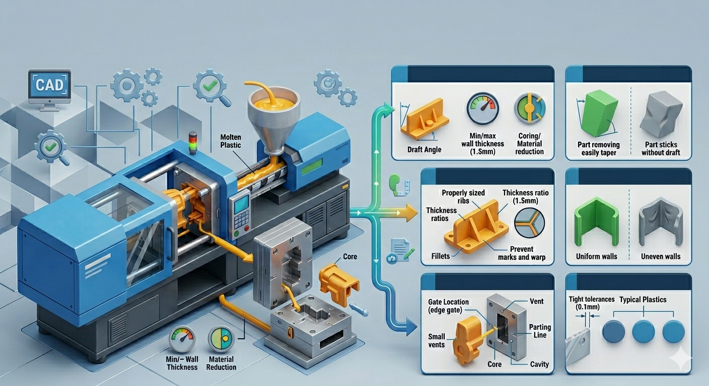
In injection molding, product quality is often determined long before production begins. Decisions made during the part design stage can directly affect tooling complexity, cycle time, dimensional stability, cosmetic appearance, and long-term manufacturing consistency.
A part that looks acceptable in CAD does not always translate into a stable and cost-efficient production process.
This is why Design for Manufacturability (DFM) plays a critical role in injection molding projects. For manufacturers, engineers, and sourcing teams, DFM is not simply about making a plastic part easier to mold.
It is a process of reducing manufacturing risk while improving production efficiency and cost predictability.
Many common injection molding problems such as sink marks, warpage, short shots, excessive flash, or premature tooling wear can often be traced back to design decisions made early in development. Correcting these issues after tooling fabrication can lead to expensive mold modifications, project delays, and additional validation work.
For companies developing industrial, automotive, electronics, or consumer products, early-stage DFM evaluation is often one of the most effective ways to improve manufacturability while controlling overall production cost.
What DFM Means in Injection Molding
Design for Manufacturability in injection molding refers to the process of optimizing part geometry so it can be produced consistently, efficiently, and economically.
The goal is not only to ensure that molten plastic can fill the cavity properly, but also to maintain stable production performance throughout the product lifecycle.
A well-designed injection molded part should support:
1. balanced material flow,
2. consistent cooling,
3. reliable ejection,
4. dimensional repeatability,
5. and reasonable tooling complexity.
In practice, DFM is a balance between product function, material behavior, tooling limitations, and production economics.
A design that prioritizes aesthetics without considering moldability may increase manufacturing challenges significantly. On the other hand, a design optimized for manufacturability can help reduce scrap rates, shorten cycle times, and improve overall process stability.
How Part Design Affects Manufacturing Cost
One of the most overlooked aspects of injection molding is how strongly part geometry influences production cost. Many cost drivers are not caused by material price alone, but by the complexity introduced during the design stage.
Wall thickness, undercuts, deep ribs, sharp corners, and unrealistic tolerances all contribute to tooling difficulty and processing instability. Even small design changes can affect cooling efficiency and cycle time.
For example, thick wall sections generally require longer cooling time before the part can be safely ejected. In many cases, cooling accounts for the largest portion of the injection molding cycle. Increasing wall thickness from 2 mm to 4 mm does not simply double cooling demand. The effect can be significantly larger due to heat retention inside the material.
Similarly, unnecessary undercuts may require side actions or lifters inside the mold. While these mechanisms are common in injection molding, they increase tooling cost, maintenance requirements, and potential downtime during long production runs.
DFM helps identify these cost drivers before tooling fabrication begins. Early adjustments are usually far less expensive than modifying hardened tooling after mold trials reveal production problems.
Maintaining Consistent Wall Thickness
Consistent wall thickness is one of the most important principles in injection molding design. Uneven wall sections often create differential cooling rates, which can lead to warpage, sink marks, residual stress, and dimensional instability.
When molten plastic cools unevenly, thicker areas shrink differently compared to thinner sections. This imbalance affects part flatness and dimensional repeatability, especially for engineering plastics with higher shrinkage characteristics.
Rather than relying on thick sections for structural strength, engineers often use ribs or gussets to improve stiffness while maintaining more uniform wall dimensions. This approach helps reduce material usage while improving cooling efficiency.
Consistent wall thickness also improves flow behavior during filling. Sudden thickness transitions can create hesitation flow or trapped air, increasing the risk of cosmetic and structural defects.
The Importance of Draft Angles
Draft angles are frequently underestimated during product development, particularly in early-stage conceptual designs. However, insufficient draft can create major production challenges once the mold enters operation.
Draft allows the molded part to release smoothly from the cavity during ejection. Without proper draft, parts may stick to the mold surface, increasing ejection force and potentially damaging cosmetic surfaces.
For textured surfaces, the draft requirement becomes even more important. Surface textures increase friction between the part and cavity wall, which means additional draft is often necessary to prevent drag marks or scratching.
In high-volume production, poor draft design can also accelerate tooling wear due to repeated friction during ejection cycles. What appears to be a small geometry decision in CAD can eventually affect mold maintenance frequency and long-term production stability.
Avoiding Sharp Corners and Stress Concentration
Sharp corners create several manufacturability concerns in injection molded parts. From a material flow perspective, sharp transitions restrict resin movement and may create localized stress areas inside the part.
From a structural standpoint, sharp corners can become stress concentration points where cracking or fatigue failure may initiate over time. This becomes more critical when using glass-filled engineering plastics, which are generally less forgiving under localized stress conditions.
Rounded transitions help improve resin flow while distributing stress more evenly throughout the geometry. Proper radii can also improve mold machining efficiency and reduce wear in high-pressure areas inside the tooling.
In many industrial applications, small radius adjustments can significantly improve both part durability and molding consistency without changing the overall product function.
Rib Design and Structural Efficiency
Ribs are commonly used in injection molding to improve stiffness without increasing overall wall thickness. However, poorly designed ribs may create cosmetic defects such as sink marks on visible surfaces.
As a general engineering approach, rib thickness is often designed thinner than the nominal wall section to reduce excessive material accumulation. Proper spacing and height ratio are also important to maintain balanced filling and cooling behavior.
Rib geometry affects more than structural performance. It also influences packing pressure distribution, cooling uniformity, and mold venting conditions.
In products requiring dimensional precision, rib placement must be carefully evaluated to prevent localized shrinkage distortion. This is particularly important for housings, covers, and structural plastic components used in industrial assemblies.
Gate Location Should Be Considered Early
Gate location is sometimes treated as a tooling decision rather than a product design consideration. In reality, gate placement directly affects manufacturability and should be evaluated during the DFM stage.
Improper gate positioning can contribute to:
1. Weld lines
2. Trapped air
3. Uneven filling
4. Excessive warpage
5. Cosmetic defects
Certain geometries may appear symmetrical visually but still experience unbalanced flow behavior during molding. Early DFM review helps identify areas where gate placement could influence final part quality.
For cosmetic parts, gate position may also affect visible surface appearance after trimming. In structural applications, weld line location can influence mechanical performance depending on load direction and material selection.
These considerations become increasingly important when using engineering-grade materials with higher viscosity or reinforced fillers.
Common Design Mistakes in Injection Molded Parts
Many injection molding production issues originate from similar design patterns. Excessively thick walls, insufficient draft, overly aggressive tolerances, and unnecessary complexity are among the most common examples.
Another frequent issue is designing features that are difficult to machine or maintain inside the tooling. Deep narrow ribs, hidden shutoff areas, and inaccessible cavity sections may increase manufacturing risk even if the part itself appears functional.
Tolerance selection is another area where practical manufacturability is often overlooked. Extremely tight tolerances across multiple dimensions may require additional tooling complexity, process control effort, and inspection resources.
In many cases, functional tolerances should be prioritized while allowing reasonable flexibility for non-critical dimensions.
DFM for Engineering Plastics
Material selection also plays a major role in DFM strategy. Different engineering plastics behave differently during molding due to variations in shrinkage, flow characteristics, thermal stability, and moisture absorption.
Glass-filled nylon, for example, provides excellent stiffness and heat resistance but may introduce higher warpage tendency depending on fiber orientation and part geometry. Polycarbonate offers good impact resistance but may require careful processing control to avoid internal stress.
POM materials provide excellent dimensional stability and low friction properties, but sharp corners and uneven wall sections can still create molding challenges.
Because of these material-specific behaviors, DFM should always be evaluated together with resin selection rather than as separate decisions.
Why Early DFM Review Matters
Injection molding projects become significantly more difficult to adjust once tooling fabrication has started. Mold modifications may require re-machining, welding, additional inserts, or process revalidation.
For this reason, early collaboration between product designers and manufacturing teams is often critical. DFM reviews performed before tooling release can help identify manufacturability concerns while design flexibility is still available.
In many projects, small design optimizations made early in development can prevent major production issues later in mass production.
Injection molding is not only about shaping plastic into a final product. It is a manufacturing system where part geometry, material behavior, tooling design, and process control are closely interconnected.
Strong DFM practices help align these elements from the beginning, improving production efficiency while reducing unnecessary cost and manufacturing risk.